Step 4: Post-processing
The fourth and final step consists in post-processing the CRATE simulation results.
CRATE generates several output files during execution time that are collectively stored in a single output directory created in the same path and sharing the same name as the input data file as shown below.
example_input_data_file.dat
example_input_data_file/
├──── example_input_data_file.screen
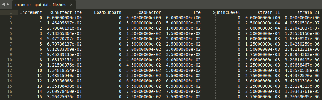
├──── example_input_data_file.hres
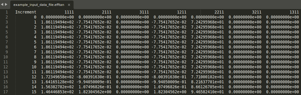
├──── example_input_data_file.efftan
├──── example_rve.rgmsh
├──── offline_stage/
│ ├──── ...
│ ├──── example_input_data_file.crve
│ └──── example_input_data_file_clusters.vti
└──── post_processing/
├──── example_input_data_file.pvd
└──── VTK/
├──── example_input_data_file_0.vti
├──── example_input_data_file_1.vti
└──── ...
Among the default output files, three are particularly relevant:
.screenfile - A log file where all the data displayed in the default standard output device is stored (usually the terminal console window, see Step 3);.hresfile - A file where incremental macro-scale loading path data and the macro-scale material response are stored, namely the homogenized strain and stress tensors computed at every macro-scale loading increment;
.efftanfile - A file where the RVE effective material consistent tangent modulus computed at every macro-scale loading increment is stored.
Besides the previous output files, two important output subdirectories are also created:
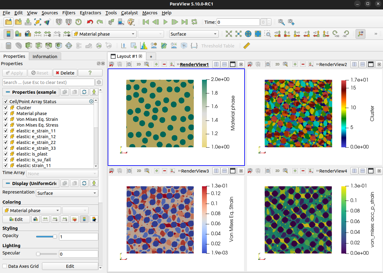
VTK/directory - This directory contains a collection of VTK XML output files (.vti), each associated with a given macro-scale loading increment. These files allow the RVE relevant physical data to be conveniently analyzed with a suitable visualization software (e.g. ParaView), as illustrated below. The VTK collection file (.pvd) is simply an aggregation file that sets the sequence of the multiple time simulation steps and allows the generation of animations.
offline_stage/directory - This directory contains several files associated with the offline-stage of the clustering-based reduced-order method, i.e., with the computation of the CRVE (see Conceptual framework). Two files are particularly relevant:.vtifile - A VTK XML output file that allows the CRVE to visualized with a suitable software (e.g. ParaView), namely the material phases and the material clusters;.crvefile - A numerical data file that stores the CRVE structural data (e.g., material clusters, cluster interaction tensors) computed in the offline-stage. This file can then be used to perform multiple analyses of the same CRVE (e.g., under different macro-scale loading conditions), while avoiding the computational cost of (repeating) the offline-stage. This option is automatically prompted to the user whenever the.crvefile is found within theoffline_stage/directory.